Upgrade Your Skills and Easily Obtain Autodesk RVT_ELEC_01101 Certification
Wiki Article
What's more, part of that DumpStillValid RVT_ELEC_01101 dumps now are free: https://drive.google.com/open?id=1CQUfRkWYXJWbGfS-YwNzhc9IXZ0wp9z6
You can use RVT_ELEC_01101 guide materials through a variety of electronic devices. At home, you can use the computer and outside you can also use the phone. Now that more people are using mobile phones to learn our RVT_ELEC_01101 study guide, you can also choose the one you like. We have three versions of our RVT_ELEC_01101 Exam Braindumps: the PDF, the Software and the APP online. And you can free download the demo s to check it out.
Autodesk RVT_ELEC_01101 Exam Syllabus Topics:
| Topic | Details |
|---|---|
| Topic 1 |
|
| Topic 2 |
|
| Topic 3 |
|
| Topic 4 |
|
| Topic 5 |
|
>> Valid RVT_ELEC_01101 Exam Prep <<
Examcollection RVT_ELEC_01101 Dumps | RVT_ELEC_01101 Cheap Dumps
All RVT_ELEC_01101 learning materials fall within the scope of this exam for your information. The content is written promptly and helpfully because we hired the most professional experts in this area to compile the RVT_ELEC_01101 Preparation quiz. And our experts are professional in this career for over ten years. Our RVT_ELEC_01101 practice materials will be worthy of purchase, and you will get manifest improvement.
Autodesk Certified Professional in Revit for Electrical Design Sample Questions (Q14-Q19):
NEW QUESTION # 14
What should an electrical designer do to associate a lighting device with light fixtures in a model?
- A. Create a switch system using the light fixtures to define the system and add the switch.
- B. Create a switch system by selecting a switch and then adding lights
- C. Create an electrical circuit including the light fixtures and switch as one selection.
- D. Create an electrical circuit using the light fixtures to define the system and add the switch.
Answer: B
Explanation:
In Autodesk Revit Electrical Design, a lighting device (switch) must be associated with lighting fixtures through a switch system, not through electrical circuits. Switch systems are independent of lighting circuits and wiring, as they are intended to represent the control relationship between a light switch and the lighting fixtures it operates.
According to the Autodesk Revit MEP User's Guide (Chapter 17 - Electrical Systems, pages 475-478), the official method is described under "Creating a Switch System."
"You can assign lighting fixtures to specific switches in a project.
The switch system is independent of lighting circuits and wiring."
(Revit MEP User's Guide, p. 475)
"To create a switch system:
Select one or more lighting fixtures in a view, and click
Modify | Lighting Fixtures tab ➤ Create Systems panel ➤ Switch.
Click Switch Systems tab ➤ System Tools panel ➤ Edit Switch System.
Click Add to System, and select one or more lighting fixtures.
Click Select Switch, and select a switch in the drawing area.
Click Finish Editing System."**
(Revit MEP User's Guide, p. 476)
How It Works:
The switch system links a lighting device (switch) with lighting fixtures, enabling Revit to manage how light fixtures respond to specific switches.
Unlike electrical circuits, which define power flow and load connections to panels, the switch system defines control logic (which lights are turned on/off by which switch).
The designer begins by selecting the switch and then adding lights to its system, ensuring all lights associated with that switch are grouped correctly.
Supporting Extract from Revit Documentation:
"You can also create a lighting switch system by right-clicking the connector for a lighting fixture and clicking Create Switch System." (Revit MEP User's Guide, p. 475)
"Add lighting fixtures to the switch system...
Click Select Switch and select a switch in the drawing area."
(Revit MEP User's Guide, p. 476)
"The switch system is independent of lighting circuits and wiring."
(Revit MEP User's Guide, p. 475)
Conclusion:
To associate a lighting device (switch) with light fixtures in a Revit electrical model, the designer must create a switch system. This is done by selecting the switch, then adding the desired lighting fixtures to that system using the Add to System and Select Switch tools under the Switch Systems tab.
NEW QUESTION # 15
Refer to exhibit.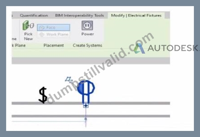
An electrical designer is circuiting a dwelling unit. The receptacle (electrical fixture) shown must be controlled by the switch (lighting device) shown to switch a plug-in lamp When the receptacle is selected, Revit does not provide an option to add the receptacle to a switch system.
What is causing this issue?
- A. Only lighting fixtures can be added to switch systems.
- B. The receptacle's "Switchable" option Is not selected within the family editor.
- C. The switch and the receptacle are not on the same circuit
- D. A switch system has not yet been created.
Answer: B
Explanation:
In Autodesk Revit Electrical Design, when an electrical designer attempts to control a receptacle (an Electrical Fixture family) with a switch (a Lighting Device family) as part of a switch system, Revit will only allow this connection if the receptacle's family has been configured as Switchable within the Family Editor.
According to the Autodesk Revit MEP User's Guide (Chapter 17 - "Electrical Systems"):
"Revit allows you to add elements such as lighting fixtures or receptacles to a switch system only if the family includes a switchable connector. The 'Switchable' parameter must be enabled in the Family Editor to allow this connection." This means that for the receptacle shown in the exhibit to appear as an available component for switching, the Electrical Connector within its family must have the Switchable property checked. This parameter is found under:
Family Editor → Select Connector → Properties Palette → Electrical - Data → Switchable.
If this option is not enabled, Revit treats the receptacle as a standard unswitched outlet and will not display it in the switch system creation dialog. Once the option is checked, the designer can reload the family into the project and associate it with a switch system normally.
Additionally, the Smithsonian Facilities Revit Template User's Guide explains this concept as follows:
"To associate receptacles with lighting switches, ensure that the receptacle family has a switchable connector. Without this setting, the device will not appear as an assignable component to a switch system." This distinction is important in residential electrical modeling, where switched receptacles are common for plug-in lamps. Lighting circuits can include both Lighting Fixtures and Switchable Receptacles when the family configuration supports it.
Incorrect Options Explanation:
A . A switch system not being created is irrelevant - the issue occurs before system creation.
C . Being on the same circuit doesn't affect switchability; it affects electrical load connection.
D . Incorrect - Revit supports switchable receptacles if properly configured.
Therefore, the correct answer is B. The receptacle's "Switchable" option is not selected within the family editor.
References:
Autodesk Revit MEP User's Guide - Chapter 17 "Electrical Systems," pp. 417-421 Autodesk Revit Electrical Design Essentials - Section "Creating and Editing Electrical Fixtures and Switch Systems" Smithsonian Facilities Revit Template User's Guide - Section 8.4 "Switchable Receptacle Family Standards," p. 89
NEW QUESTION # 16
An electrical designer needs to add a drafting view to a model from another project. What is the method to do this?
- A. Select Transfer Project Standards, select the desired project, and then select the drafting view.
- B. Select Link Revit, browse to the desired model, and then select desired drafting view
- C. Select Insert from File, select Insert Views from File, browse to the desired project, and then select the drafting view.
- D. Select Open, select the desired project, right-click the desired drafting view, and then copy/paste
Answer: C
Explanation:
In Autodesk Revit, a drafting view is a 2D view that contains detail information not directly associated with the model. When an electrical designer needs to reuse a drafting view from another project (for example, standard details or symbols), the correct method is to use the Insert Views from File command under the Insert tab.
The Autodesk Revit MEP User's Guide - Chapter 48 "Detailing" (page 1072) describes the process as follows:
"Inserting a Drafting View from Another Project
Click Insert tab ➤ Import panel ➤ Insert from File drop-down ➤ Insert Views from File.
In the Open dialog, select a project file, and click Open.
The Insert Views dialog opens, displaying all the views that are saved in that project.
Select the desired drafting views and click OK."
(Revit MEP User's Guide, p. 1072)
This command imports the drafting view into the current Revit model while preserving annotations, filled regions, detail components, and text. It ensures that any standard electrical symbols, notes, or schematics created previously can be directly reused without rebuilding the detail from scratch.
If any duplicate type names exist, Revit automatically uses the types and properties from the current project, displaying a warning if necessary.
"Revit MEP creates a new drafting view with all the 2D components and text. If you have duplicate type names, the type name and properties from the current project are used." (Revit MEP User's Guide, p. 1072) Supporting Documentation Extracts:
"Saving Drafting Views to an External Project
Select a drafting view in the Project Browser.
Right-click the view name, and click Save to New File."
(Revit MEP User's Guide, p. 1071)
"The saved project can then be used later to insert drafting views into another Revit project using Insert Views from File." (Revit MEP User's Guide, p. 1072)
NEW QUESTION # 17
Refer to exhibit.
(The image is presented in Imperial units: 1 In = 25 mm [Metric units rounded].)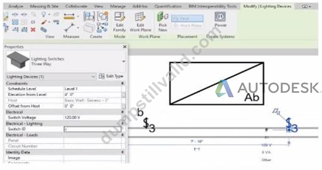
An electrical designer is trying to add the selected three-way switch to the existing switch system "b". The designer is unable to add the switch to the switch system.
Why is this problem occurring?
- A. Revit is not in Edit Switch System mode.
- B. A switch system can contain only one switch.
- C. The switch's Switch ID parameter does not match the switch system.
- D. The switch is not powered.
Answer: C
Explanation:
In Autodesk Revit Electrical Design, lighting control systems such as single-pole, three-way, and four-way switches are managed using Switch Systems. These systems logically connect lighting devices (switches) to the lighting fixtures they control. For multiple switches (like three-way configurations) to be part of the same control circuit, they must share the same Switch ID value.
In the exhibit, the electrical designer is attempting to add a three-way switch to the existing switch system labeled "b", but Revit does not allow it. The reason is that the Switch ID parameter of the new switch does not match the Switch ID of the system it is intended to join.
The Switch ID acts as the unique identifier that links all switches controlling the same group of fixtures. If the IDs differ (for example, "b3" versus "b"), Revit interprets them as belonging to separate systems and prevents them from being grouped together.
The Autodesk Revit MEP User's Guide - Electrical Systems: Lighting and Switch Systems explains this clearly:
"Switch systems are organized by Switch ID. All switches controlling the same lighting circuit must have identical Switch ID values. Revit will not allow a switch to be added to an existing system if its Switch ID does not match that system's identifier." To fix this, the designer must:
Select the three-way switch.
In the Properties palette, locate the Switch ID parameter.
Change its value to match the target switch system's ID (in this case, "b").
Once both switches share the same Switch ID, Revit will successfully include them in the same Switch System.
NEW QUESTION # 18
Refer to exhibit.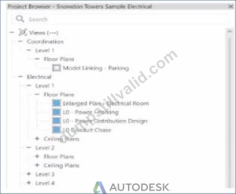
An electrical designer wants to organize the Protect Browser as shown in the exhibit. Select the correct options in order to achieve the desired organization. (Select three.)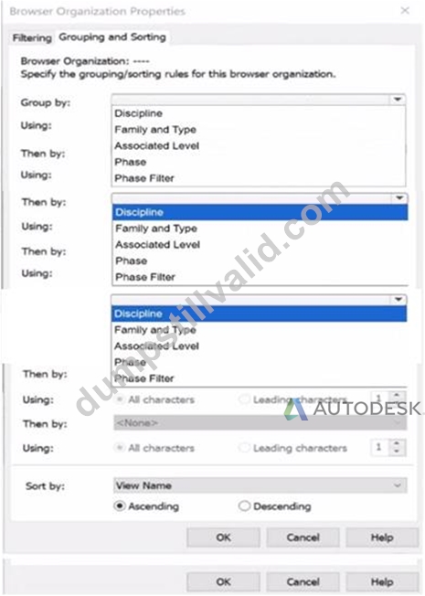
Answer:
Explanation: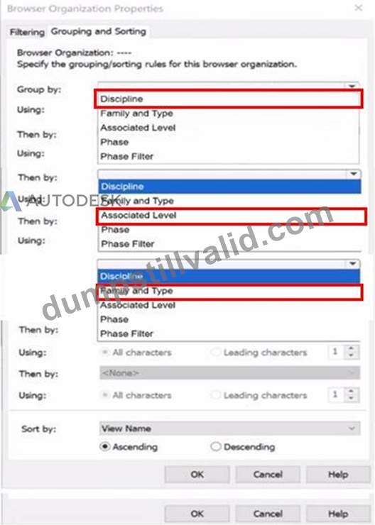
NEW QUESTION # 19
......
Our DumpStillValid RVT_ELEC_01101 exam certification training material is the collection of experience and innovation results of highly certified IT professionals in IT industry. We guarantee that after you buy DumpStillValid RVT_ELEC_01101 certification exam training materials, we will provide free renewal service for one year. If RVT_ELEC_01101 Exam Certification training materials have any quality problem or you fail RVT_ELEC_01101 exam certification, we will give a full refund unconditionally.
Examcollection RVT_ELEC_01101 Dumps: https://www.dumpstillvalid.com/RVT_ELEC_01101-prep4sure-review.html
- RVT_ELEC_01101 Test Pass4sure ???? Valid RVT_ELEC_01101 Exam Papers ⏪ RVT_ELEC_01101 Braindumps Downloads ???? Download ⮆ RVT_ELEC_01101 ⮄ for free by simply searching on 《 www.vce4dumps.com 》 ????RVT_ELEC_01101 Knowledge Points
- Unique Features of Pdfvce's Autodesk RVT_ELEC_01101 Practice Test (Desktop and Web-Based) ???? Open 【 www.pdfvce.com 】 and search for 「 RVT_ELEC_01101 」 to download exam materials for free ????RVT_ELEC_01101 Minimum Pass Score
- Latest RVT_ELEC_01101 Exam Registration ???? Test RVT_ELEC_01101 Pdf ↘ RVT_ELEC_01101 Test Questions Vce ???? Search on ▷ www.prepawaypdf.com ◁ for ⇛ RVT_ELEC_01101 ⇚ to obtain exam materials for free download ????RVT_ELEC_01101 Free Exam Dumps
- Autodesk RVT_ELEC_01101 Exam | Valid RVT_ELEC_01101 Exam Prep - Free PDF of Examcollection RVT_ELEC_01101 Dumps Products ???? Open ☀ www.pdfvce.com ️☀️ enter ▷ RVT_ELEC_01101 ◁ and obtain a free download ????RVT_ELEC_01101 Knowledge Points
- Unlimited RVT_ELEC_01101 Exam Practice ???? RVT_ELEC_01101 Test Pass4sure ???? Valid Exam RVT_ELEC_01101 Registration ???? Search for ▷ RVT_ELEC_01101 ◁ and download it for free on ⮆ www.practicevce.com ⮄ website ????RVT_ELEC_01101 Knowledge Points
- RVT_ELEC_01101 Exam Engine ???? Latest RVT_ELEC_01101 Dumps Files ???? Test RVT_ELEC_01101 Pdf ???? Search for ⇛ RVT_ELEC_01101 ⇚ and download it for free immediately on ⇛ www.pdfvce.com ⇚ ↗RVT_ELEC_01101 Reliable Exam Sample
- Trustworthy Valid RVT_ELEC_01101 Exam Prep | Amazing Pass Rate For RVT_ELEC_01101: Autodesk Certified Professional in Revit for Electrical Design | Authorized Examcollection RVT_ELEC_01101 Dumps ???? Search for ▛ RVT_ELEC_01101 ▟ and download exam materials for free through 【 www.prepawaypdf.com 】 ????Valid Exam RVT_ELEC_01101 Registration
- RVT_ELEC_01101 Demo Test ???? RVT_ELEC_01101 Knowledge Points ⛴ Test RVT_ELEC_01101 Pdf ???? Search for ➥ RVT_ELEC_01101 ???? and obtain a free download on ▶ www.pdfvce.com ◀ ????RVT_ELEC_01101 Test Pass4sure
- Latest RVT_ELEC_01101 Exam Registration ???? Test RVT_ELEC_01101 Pdf ???? RVT_ELEC_01101 Minimum Pass Score ???? Go to website 「 www.pass4test.com 」 open and search for 「 RVT_ELEC_01101 」 to download for free ????RVT_ELEC_01101 Exam Certification Cost
- Valid Exam RVT_ELEC_01101 Registration ???? Valid RVT_ELEC_01101 Exam Papers ???? RVT_ELEC_01101 Accurate Test ???? The page for free download of 【 RVT_ELEC_01101 】 on “ www.pdfvce.com ” will open immediately ????RVT_ELEC_01101 Exam Certification Cost
- RVT_ELEC_01101 Accurate Test ???? RVT_ELEC_01101 Braindumps Downloads ???? RVT_ELEC_01101 Free Exam Dumps ???? Search for ▷ RVT_ELEC_01101 ◁ and download it for free on “ www.vceengine.com ” website ????RVT_ELEC_01101 Knowledge Points
- pennywznb347777.illawiki.com, nanniekgws880120.angelinsblog.com, e-web-directory.com, kianaqhwi991207.blogdanica.com, vidyakalpa.com, deborahmvtf300162.thenerdsblog.com, arrantnkg060027.blogs100.com, www.stes.tyc.edu.tw, keziauvas798138.topbloghub.com, www.stes.tyc.edu.tw, Disposable vapes
What's more, part of that DumpStillValid RVT_ELEC_01101 dumps now are free: https://drive.google.com/open?id=1CQUfRkWYXJWbGfS-YwNzhc9IXZ0wp9z6
Report this wiki page